If you’re working on anything that needs custom metal components – whether it’s a one-off prototype or a full production run – you’ve probably come across the term CAD more than a few times. Short for Computer-Aided Design, CAD plays a big part in the metal fabrication design process, especially when precision and speed matter.
From reducing the back-and-forth between design and production to keeping things accurate down to the millimetre, CAD for metal fabrication is more or less the quiet engine behind many bespoke projects.
So, what exactly does it do, and why does it matter so much for those after something built to spec?
What is CAD?
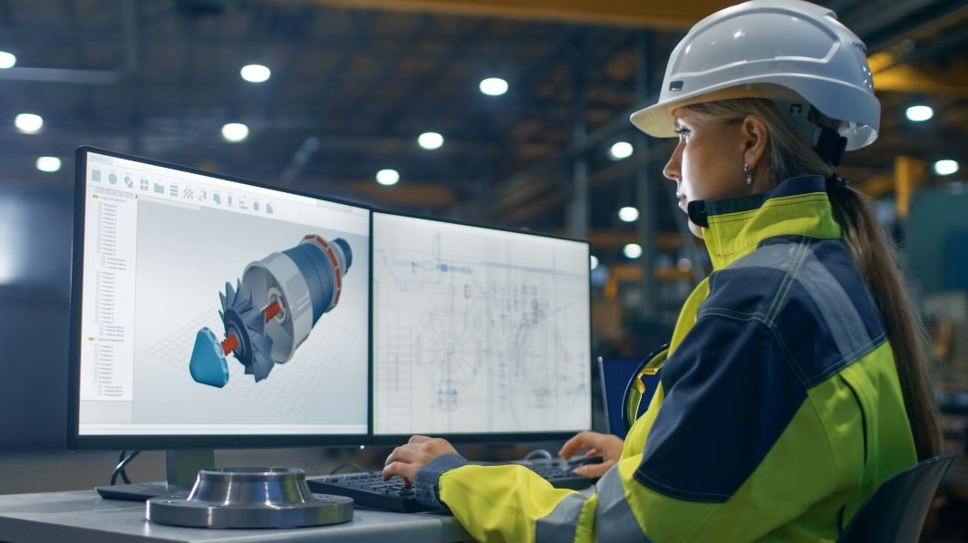
You’ll often hear people describe CAD as just a fancy digital sketchpad – but it’s quite a bit more than that. Short for Computer-Aided Design, CAD refers to specialised software that helps engineers and designers create accurate 2D and 3D models of physical parts. In metal fabrication, it’s often the very first step in turning a rough idea into a part that can actually be made.
CAD makes it easier to visualise how something will look and function before a single piece of metal is touched. It lets you rotate models, check measurements, simulate real-world forces and fine-tune every cut, bend, and bracket – all on screen. That’s a big step up from hand-drawn blueprints.
It’s come a long way since the early 2D-only systems of the 1960s and 70s.
Today’s CAD tools are intuitive, powerful, and built for precision, which is exactly what bespoke metal fabrication demands. They’re used not just for design, but for checking tolerances, avoiding costly errors, and making sure custom metal components are made right the first time.
Why is CAD Important for Bespoke Metal Projects?
Standard parts might work for some builds, but bespoke metal fabrication is usually a different story. Projects often come with tighter tolerances, tricky shapes, or unique design features that can’t be handled with a one-size-fits-all approach. That’s where CAD steps in. It gives engineers the flexibility to adapt every element of a design so the finished part isn’t just close – it’s spot on.
Take, for example, a custom ventilation panel for an enclosure. With CAD, you can adjust every cut-out, corner radius, and fixing point, knowing it’s going to align with the rest of the build perfectly. There’s no need to cross your fingers and hope it fits – you can test, simulate and refine it before the first cut’s even made.
This level of control is why CAD has become a core part of how Greengate approaches sheet metal design & prototyping. Whether it’s a single bracket or a complex enclosure, CAD allows us to meet specifications confidently and efficiently. It’s not just about looking good on paper – it’s about delivering a part that performs exactly as expected.
In short, CAD makes it possible to move from a custom concept to a physical part without second-guessing the outcome. That’s a big win when precision matters.
How CAD Makes Metal Fabrication More Efficient
Time and accuracy tend to pull in opposite directions – but CAD has a way of bringing them together. In bespoke metal fabrication, where changes are common and details matter, CAD speeds up the entire design-to-production cycle without losing sight of quality.
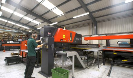
One of the biggest advantages is how CAD files connect directly to modern machinery. For instance, with CNC metal laser cutting, digital designs are sent straight to the laser cutter. This removes the need for manual programming, helping reduce both setup time and the chance of costly errors.
Designers and fabricators can also work more closely. If something’s not quite right – say, a hole’s in the wrong spot or a bend doesn’t work with the material – CAD allows for fast adjustments. You’re not starting from scratch each time. That responsiveness is key for prototyping or short runs where every second counts.
Other time-saving benefits include:
- Better use of raw materials through smart nesting
- Instant updates to all parts of a design when one change is made
- Easier file sharing and version control across teams
- Fewer errors caused by misinterpretation of technical drawings
So whether it’s a first draft or final spec, CAD brings a level of clarity and speed that makes the whole process more efficient from top to bottom.
Challenges of Using CAD
For all its strengths, CAD isn’t without a few bumps along the way. Some of the most common challenges in CAD metalwork don’t come from the tools themselves, but from how people use them, or how well they work with the rest of the process.
For example, if the design and fabrication teams aren’t working closely, even the most detailed CAD file can miss the mark. Then there’s the learning curve – CAD software has plenty of features, but it takes time to get the most out of them.
You might also run into issues like:
- Incompatibility between different CAD file formats
- Limited in-house skills for advanced CAD prototyping in metal fabrication
- Design files that don’t reflect real-world constraints like tooling limits or material behaviour
One way around these? Partnering with an experienced fabricator, such as ourselves at Greengate Metal Components, who are used to working from CAD models. We can spot problems early, recommend adjustments, and help translate ideas into workable solutions without too much friction.
CAD has become more than just a design tool – it’s a key part of how bespoke metal fabrication actually works. From the first sketch to the final cut, it supports precision, reduces waste, and keeps projects moving smoothly. Whether you’re dealing with tight tolerances, last-minute changes, or one-off prototypes, CAD gives you the control and visibility needed to get it right.At Greengate Metal Components, we use CAD across every stage of our sheet metal fabrication process – combining technical know-how with real-world practicality to deliver custom components that just fit.