20 Jan 2026
Why Are Certain Sheet Metal Features Expensive to Punch?
Punching is a controlled shearing process governed by force, clearance and tool condition. On a drawing, a hole or slot...

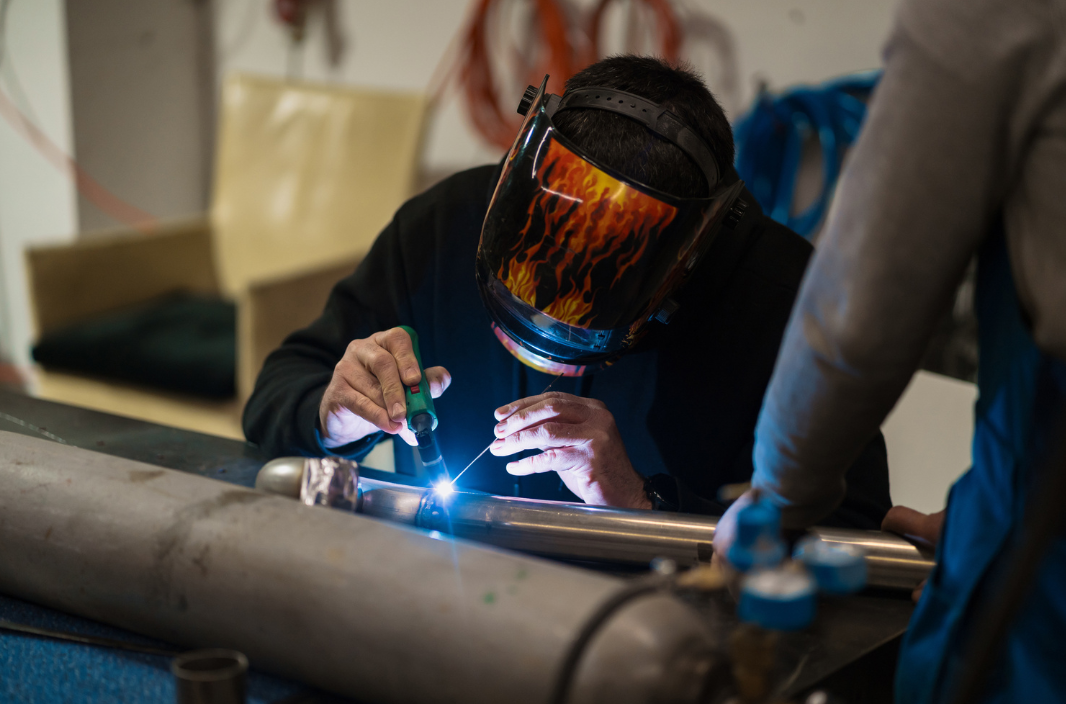
Welding distortion is not random. It is the predictable result of thermal expansion followed by constrained contraction.
When weld metal is deposited, the localised zone expands under heat. As it cools, it contracts and if that contraction is restrained by surrounding material, tensile residual stress forms. If it is free to move, then geometry shifts. Both outcomes influence dimensional accuracy.
Most welding distortions originate in the design phase rather than on the shop floor. Weld length, joint type, material thickness, sequencing and restraint conditions all determine how shrinkage forces redistribute through a structure.
For engineering and design firms developing welded assemblies, distortion control begins with understanding shrinkage vectors and heat input distribution before fabrication starts.
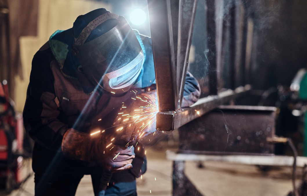
Weld metal contracts along its longitudinal axis during cooling. That contraction pulls material toward the weld centreline. In asymmetric layouts, this pull creates bending moments that result in angular distortion or bowing.
A single fillet weld applied to one side of a plate will typically cause angular rotation toward the weld. Mirroring that weld on the opposite side balances contraction forces and reduces net movement.
Distortion mechanisms to consider include:
Breaking long welds into staggered segments reduces continuous heat input. Alternating weld locations distributes thermal load more evenly. Symmetry in layout reduces directional bias in contraction forces.
Balanced weld layouts do not eliminate welding distortions, but they reduce the magnitude of movement and simplify dimensional control.
Heat input is typically expressed as:
Heat input kJ per mm equals Voltage × Current divided by Travel Speed × 1000
Increased heat input leads to a larger weld pool and expands the heat-affected zone (HAZ). A larger HAZ, in turn, increases the volume of shrinkage and the concentration of residual stress.
Furthermore, the geometry of the joint has a direct impact on heat concentration.
| Joint Type | Heat Concentration | Distortion Sensitivity |
| Butt Joint | High along centreline | Sensitive to fit-up accuracy |
| Fillet Joint | Localised at toe regions | High angular distortion risk |
| Lap Joint | Distributed across overlap | Moderate shrinkage effects |
Oversized welds increase deposited metal volume. More deposited metal equals more contraction during cooling. Over-welding is a frequent cause of distortion.
Effective weld joint design tips include:
Heat input welding control begins at design stage by limiting weld volume and selecting joint geometry that spreads thermal energy rather than concentrating it.
Joint selection influences how shrinkage forces are transmitted through the structure.
Butt joints with accurate fit-up distribute contraction evenly across thickness. Poor fit-up concentrates stress and increases angular rotation.
Fillet welds introduce asymmetrical heating through plate thickness, producing rotational distortion if not balanced.
When to avoid over-welding:
Reducing weld metal volume reduces contraction strain. Lower contraction strain reduces residual tensile stress locked into the weld zone. This directly reduces weld rework during dimensional inspection.
Material thickness strongly influences distortion behaviour.
Thin sections are more prone to buckling under compressive stress created by shrinkage. Thicker sections resist bending but retain heat longer, increasing HAZ width.
Joining thin to thick sections introduces uneven cooling rates. The thin section contracts faster, pulling against the thicker member. This creates stress concentration at the interface.
Design strategies to minimise distortion in fabrication include:
Thicker material is not always more stable. It may increase heat input requirement and prolong cooling time, intensifying residual stress formation.
Welding sequence determines how residual stress accumulates.
If welds are applied sequentially in one direction, contraction builds progressively, pulling the structure along the weld path.
Controlled welding sequence design alternates sides and distributes heat to allow partial cooling between passes. This reduces cumulative distortion.
Design must allow:
Restricted access forces welders to adjust the sequence, often increasing heat concentration in confined areas.
Access constraints also increase the risk of inconsistent travel speed, which alters heat input and affects shrinkage magnitude.
Sequencing should be considered during CAD modelling, not left to workshop improvisation.
Restraint influences distortion outcome.
If a weldment is free, it moves during cooling. If it is heavily restrained, residual stress remains locked in the structure.
Metal fabrication fixturing must balance control with controlled compliance. Over-constraining a weldment may hold geometry during welding but release distortion once clamps are removed.
Effective fixture planning includes:
Datum strategy ensures dimensional repeatability across batches. Fixtures should guide movement rather than suppress it entirely.
Early integration of fixture points in design reduces trial-and-error correction later.
Post-weld correction often includes grinding, straightening and localised heat treatment. Each introduces additional handling and potential dimensional drift.
Design features that reduce post-weld correction avoidance include:
Where dimensional precision is critical, machining allowances should be built into design rather than relying on manual straightening.
Weld distortion control is most effective when shrinkage behaviour is anticipated rather than corrected.
Welding distortions originate from thermal expansion, contraction and residual stress redistribution. Design decisions determine how these forces interact long before fabrication begins.
Greengate Metal Components applies controlled welding sequence planning, balanced joint layouts and disciplined fixturing within its metal welding fabrication processes. Early technical collaboration allows distortion risks to be assessed at the drawing stage rather than corrected after assembly.
For engineering teams seeking to reduce weld rework and stabilise fabrication performance, contact us with assembly drawings, material specifications and tolerance requirements for review.

Punching is a controlled shearing process governed by force, clearance and tool condition. On a drawing, a hole or slot...
Mixed alloy production runs expose weaknesses in parameter control faster than single-material jobs. Aluminium, stainless steel and carbon steel respond...
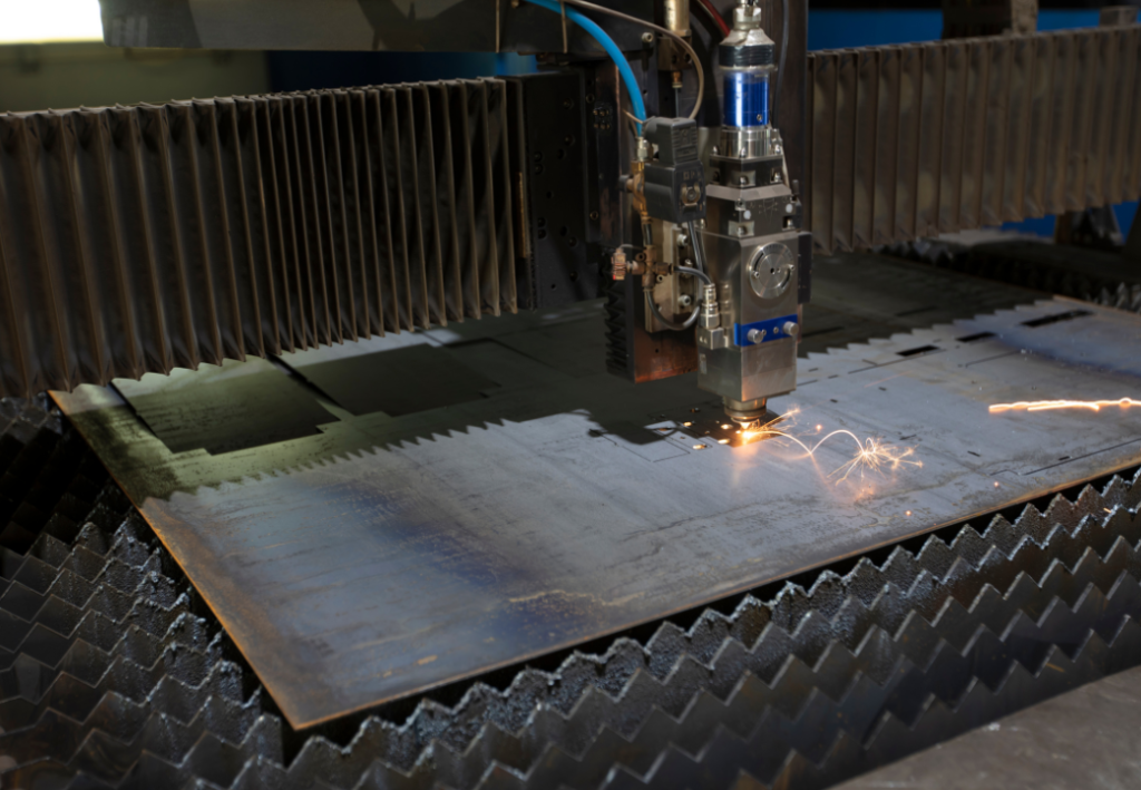
CNC cutting edge quality is a measurable output of thermal control, gas stability and machine calibration. It is not cosmetic....